Bionic Bulldogs #21502
We are team 21502, the Bionic Bulldogs from North Carolina. We are part of a five-team group called Creekside Robotics. This is our team's third season together. Some of us came up from the middle school teams in Creekside, and others started on the high school teams. Our middle school teams are Bots by the Creek 15707 and Boltiverse 21490. Our fellow High school team is Entropic Fluctuations #19410.
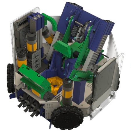
Power Play 2022-2023
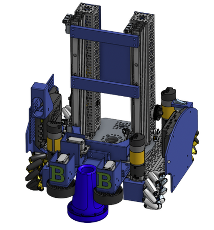
Center Stage 2023-2024
The Team
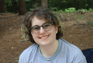
Emma
Senior
3rd FTC Season
Scouting
Mechanical
CAD
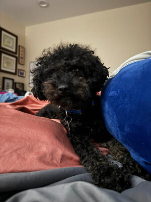
JD's Dog JC
JD
Senior
3rd FTC Season
CAD
Programming
Mechanical
Xander
Junior
5th FTC Season
Programming
Eli
Sophmore
4th FTC Season
Mechanical
CAD
Caleb
Sophmore
2nd FTC Season
CAD
Mechanical
Dean
Sophmore
2nd FTC Season
Programming
Dylan
Sophmore
2nd FTC Season
Mechanical

Alex
Freshman
3rd FTC Season
Programming